iBox components are created as any other assembly controlled by a single skeleton. For more information about the skeleton design method, see our "How To" section. With this skeleton, it is required that its initial geometry is controlled by three parameters:
| 1. | Width |
| 2. | Depth |
| 3. | Height |
The parameter names can be freely chosen to make them easy to read and understand for the user. It is possible that changing one of the parameters does not result in changes to the overall skeleton geometry. For example, a block of facade doors with hinges. Width and height parameters are important for such component, while depth parameter may have no effect on the doors, since the door depth does not change regardless of the measurements of the interior skeleton body. In this case, such parameter can be created as a dummy parameter that has no effects on the geometry of the door skeleton.
Another requirement for the iBox component: the assembly created based on the skeleton must have at least two iMate connections. One connection has to define the orientation of the front and top part of the iBox component. All other iMate connections are set depending on the user’s needs and are auxiliary in nature, i.e. they allow displaying accurately the component in the context of the interior.
For Woodwork for Inventor to see such an assembly as an iBox component, it has to be published. To publish the component, open the file of the assembly which will be transformed into the iBox component. Open the iBox publish command.
To open the command, go to:
Manage -> iBox Author ![]()
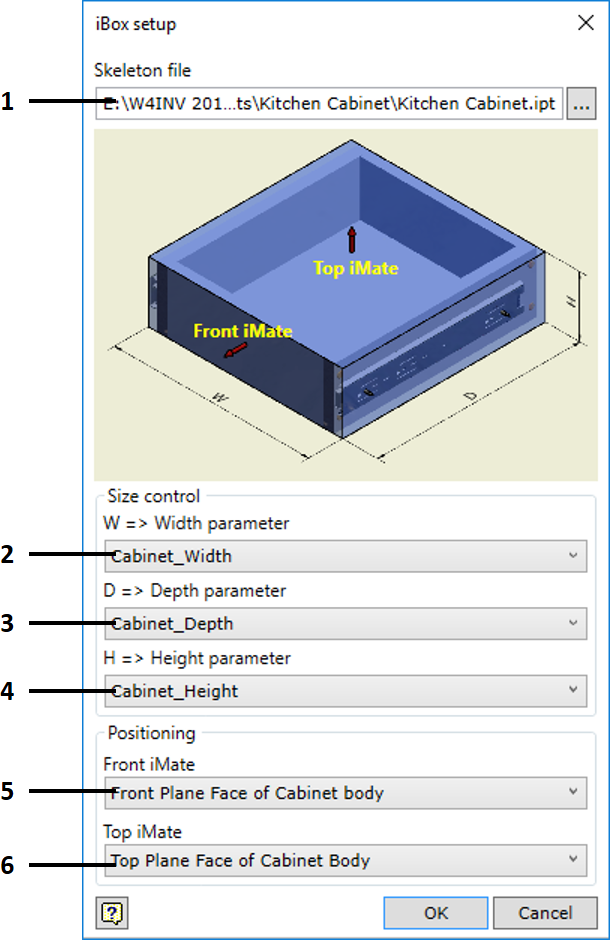
| 1. | Selecting the skeleton body. Here, the file of the skeleton body controlling the geometry of the iBox component is selected. |
| 1. | Selecting the parameter that controls the width of the skeleton. The dropdown list includes all parameters stored in the skeleton file. |
| 2. | Selecting the parameter that controls the depth of the skeleton. The dropdown list includes all parameters stored in the skeleton file. |
| 3. | Selecting the parameter that controls the height of the skeleton. The dropdown list includes all parameters stored in the skeleton file. |
| 4. | Selecting the iMate connection for the front part. The dropdown list includes all iMate connections created for the published assembly. iBox components must have such an iMate connection. This connection has to be "Flash" type. |
| 5. | Selecting the iMate connection for the top part. The dropdown list includes all iMate connections created for the published assembly. iBox components must have such an iMate connection. This connection has to be "Flash" type. |
Once the command is completed, the assembly will be published as the iBox component.
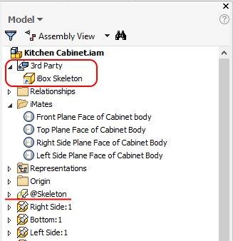
The fact that this component has been successfully published as the iBox component is confirmed by an automatically created 3rd Party sub-section (entry) in the iBox Skeleton section. If this section is deleted, the component will turn back into a regular assembly. iBox assembly file and publish command can be opened at any time to change the parameter and iMate connection settings.
Important!
Using iLogic rules with iBox components
iBox components do not limit the possibility to create various iLogic rules controlling the component. The user can create iLogic dialog boxes controlling the configuration of the iBox component. When using iLogic, one should keep in mind that, when inserting the iBox component, a copy of the iBox assembly and its skeleton file is automatically created with all the existing interconnections. However, names of files that make up the assembly are changed. So, if your rule controls any file in the assembly, keep in mind that a link to the parameter inside the part based on the file name will become invalid (once iBox is inserted). This is particularly important if links are made to a skeleton file from the assembly level. In this case, we recommend inserting the skeleton file into the entire iBox assembly after marking it as a reference or phantom component.
In the side browser, change the node display name so that it begins with “@” followed by any name understandable to the user (for example, as shown in the figure above, the underlined name “@Skeleton”). “@” is used to disable changes to the node display name introduced when using Visibility Control->Nodes command. Be sure to keep in mind that only Woodwork for Inventor “Rename Browser Nodes” command responds to this exception. While Autodesk Inventor “Rename Browser Nodes” command does not respond to these restrictions and can break the iLogic rule described below. Once the display name is changed, you can enter the iLogic rule that refers to parameters of the given file. This is done via the component display name, not the file name. iLogic rule allows such a method of controlling parameters of sub-components. Now, the name in the iBox copy will remain unchanged after inserting the iBox and iLogic rules retain the correct links to parameters of sub-components.
Location for saving iBox components.
iBox components can be saved in the project or library environment. A better practice is to store iBox components in the library environment, since it allows clearly separating the original iBox components from their copies stored in the specific interior projects. When inserting an iBox component, copies of components making up the iBox assembly are automatically created. The copying function of the iBox insert command does not copy the components included in the iBox assembly saved in the library environment but reuses them. This is the normal operating practice of Autodesk Inventor.
However, there are components that need to be copied because they are changed in the design process. So how does the copying function decide which components should be copied and which should be reused, if all components that make up the iBox assembly are stored in the library environment? For this purpose, the program includes a functionality that allows selecting any directory from the library environment in the Autodesk Inventor project and using it as the location to save iBox components. This informs the copying function that the components stored in this special directory have to be copied rather than reused. Therefore, various types of hardware stored outside this special directory will be reused in the iBox assembly, while iBox parts from this special directory will be copied to the workspace for further modification. Such a special library directory used to save iBox components that are to be copied can be selected for any Autodesk Inventor project. This can be done through Woodwork for Inventor settings. To read more, click here.