To open the command for cutting the material with a saw blade, go to:
Woodwork CAM -> Cut 
A dialog window will appear once you open the command.
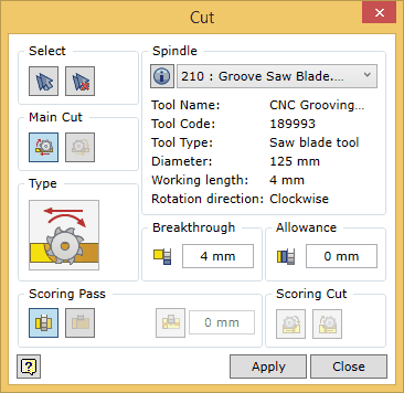
To successfully run the command, the user should follow a certain sequence for specifying data. Below you will find the description of the control of the command in the sequence that needs to be followed when performing tasks in the Pocket command window.
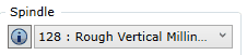
 . A window for editing spindle data will appear. In this window you can also edit all data related to cutting modes (cutting feedrate, rotation speed of the spindle, etc.). The data changes can be saved in the following ways:
  Selecting geometry in the material cut command
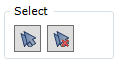
| 1. | Selection of individual part surfaces. |
| 2. | Automatic selection of surfaces for cutting. |
| 3. | Clearing the set of surfaces. |
| 4. | A cutting surface expressed as a flat Autodesk Inventor surface. |
Selection of individual elements
Surfaces that are suitable for the Woodwork for Inventor CAM Cut operation are those surfaces of the part model that are flat and their normal can make up a 180 degree angle with the tool axis and they are not bounded by other surfaces which would hinder the cutting operation (see fig. below). A possib vector of the tool’s spatial orientation is specified when configuring the machine’s spindles.
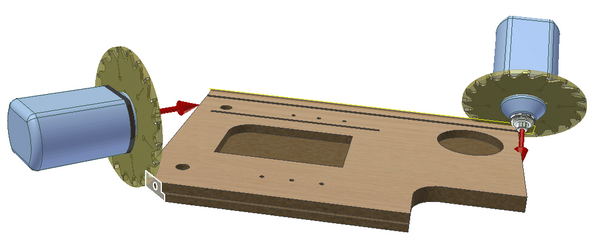
You can check if the surface can be included in the set by placing the cursor on the desired surface. Such a surface will be highlighted in white. The inclusion of the surface in the set is performed by selecting this surface with the mouse cursor. Once the surface has been included in the set, it is highlighted in blue. To remove a surface from the set, you need to select the surface while pressing and holding the Ctrl key.
 Automatic selection of surfaces
This option automatically selects surfaces that may be specified as cutting surfaces in the Cut operation, taking into consideration a possible tool orientation in space. In case the processed rectangle workpiece of the part does not have oversize on the given side, it is considered that the external surfaces of the part obtained in cutting the raw material board does not require additional processing. Therefore, they are not included in the set of automatically selected surfaces.
 Clearing the set of surfaces
Clears the current set of millable surfaces.
A cutting surface expressed as a flat Autodesk Inventor surface
Sometimes there is a need to indicate cutting without modeling it directly in the part body. In this case you can draw the line sketch and stretch it as a surface. In this way we will obtain geometry that can be specified as a cutting surface.
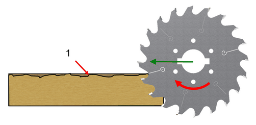
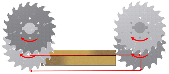
The Cut operation has specific features that require a more complex selection of the tool cutting direction than in the case of a similar Groove operation. When sawing along the entire length of the cut, there is a risk of damaging the part surface due to the saw teeth leaving the material (see fig. below). To avoid such a situation, two passes are performed:
First: Scoring Pass - cutting the top surface of the part. Second: Main Cut - final cut off to remove the piece from the part.
If you request a scoring pass in the command, you can adjust the cutting type both for the scoring pass and for the main cut.
When setting the cutting direction in the cut operation, there are two available options for each pass:
By default, the user is always offered a cutting option that is consistent with the climbing cutting for the both passes.
|


The following options can be selected for the scoring cut of the part:
|


Setting the breakthrough sawing depth
Setting the sawing allowance for withdrawing the saw blade from the indicated surface
Sets the value for withdrawing the saw blade from the cutting surface. |