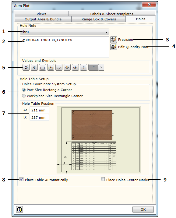
Holes - this tab is used to set hole annotation forms and placement parameters of automatically generated tables of holes cut in a part.
There are two areas designated in the hole set up settings.
| • | Hole Note - hole annotation settings which are used to specify what an annotation placed for the marked hole should look like. Woodwork for Inventor offers the Hole Annotation command for placing hole annotations. |
| • | Hole Table setup - automatically generates parameters for table placement in the sheet. |
The description below presents each option which can be selected when adjusting hole annotation and table placement.
1. Selection of hole type for describing annotation format. Woodwork for Inventor has annotations for the following hole types.
|
a. Thru - a through hole. b. Thru Counterbored - a through counterbored hole. c. Thru Countersink - a through conical hole. d. Blind - a blind hole e. Blind Counterbored - a blind counterbored hole. f. Blind Countersink - a blind conical hole. |
2. Annotation form editor. In this editor, the annotation form can be created in the same way as in the Autodesk Inventor style editor. This is performed by editing the annotation form in a dimension tab (Notes and Leaders).
3. Precision - precision adjustment by generating values describing a hole in hole tables and annotations. The Use Global option means that precision will be selected based on the specified precision of Autodesk Inventor units which are in indicated in a part.
4. Edit Quantity Note - adjustment of the form of the parameter describing the quantity of the same holes. Here, you can additionally select the following options:
a. All Holes in Part - when presenting the quantity of holes, all holes recognized in a part are calculated regardless of the drill direction. b. Holes having same drill direction only those holes that have the same drill direction are included in the hole quantity.
|
5. Buttons presented in the form of symbols. By pressing them, relevant parameters describing a hole will be entered in the editor.
![]()
Parameters listed from left to right. |
|
6. Hole table position. Automatically generated table of holes contains start coordinates of the hole which are set from the start point of the hole coordination system. The start point of the hole coordination system can be placed in:
|
a. Part Size Rectangle Corner - in the left bottom corner of the part size rectangle. b. Workpiece Size Rectangle Corner - in the left bottom corner of the workpiece size rectangle. Based on height, it is considered that the zero value of the coordination system is at the point of the part closest to the observer, looking in the direction of the part view projection. |
7. Hole Table Position - coordinates for placing the left top corner of the hole table in the sheet.
8. Place Table Automatically - request for automatic generation of the hole table for each part being placed.
9. Place Holes Center Marks - request for automatic placement of centermarks for each hole.
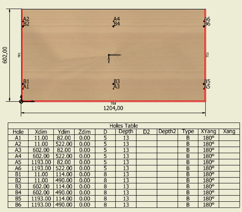
The Woodwork for Inventor Autoplot command generates one type of hole table of established form.
This table displays the following data:
Precision of the displayed units is set by adjusting annotation form settings (Precision).
|