In this section of the tutorial you will learn how to arrange required hardware and correctly configure it as well as to perform hole cutting.
If you restart Autodesk Inventor after closing it, you will find your unfinished assembly model under the name TBL.iam in the project workspace catalogue Samples/My Table.
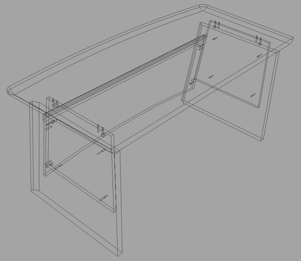
First, using Autodesk Inventor tools create axes for arranging hardware which are expressed as Work Planes in Autodesk Inventor. Open the work plane creation command: Assemble –> Work features –> Plane
Create planes as shown in the figure below. You can learn more about plane creation in the Autodesk Inventor help centre. Open it and enter the phrase Workplane in the search field and select the open Create Work Plane help section.
Confirmat connection
Start Woodwork for Inventor command for hardware arrangement.
Woodwork Design –> Joint –> Attach
In the appearing window, select place hardware component in the context of an assembly
Then in the left side of the Autodesk Inventor component selection window, select Library and in the opening library catalogue, locate Confirmat.ipt component at:
Fixed Joints\Confirmats
The dialog box is filled with Confirmat.ipt component assembly constraints.
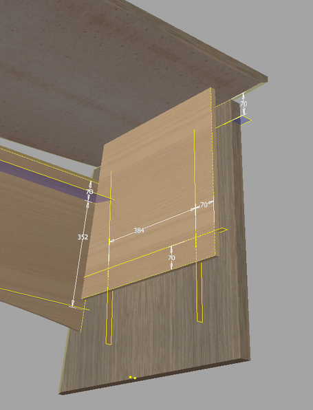
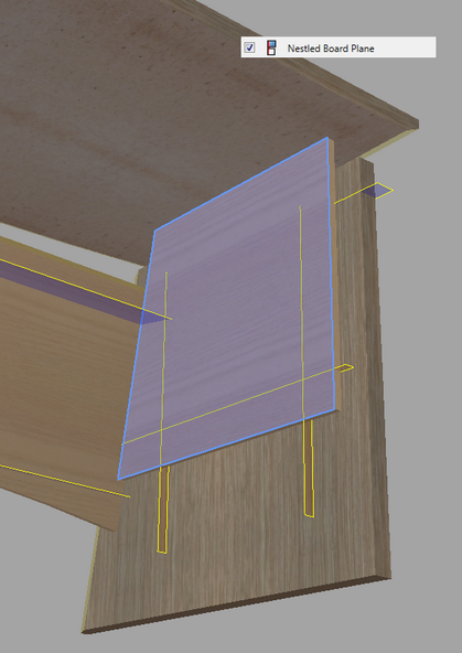
Select automatic component multiplication arrangement method First, select the Nestled Board Plane geometry. It is a plane into which a confirmat will be screwed. Select the plane as shown in the figure below.
To make the explanatory figure easier to understand, only one selected plane is shown in this figure. For the same selection, you can indicate an analogous plane on the left side of the table. In the dialog box, move the cursor to the next Axis assembly constraint and select horizontal axes as shown in the figure below.
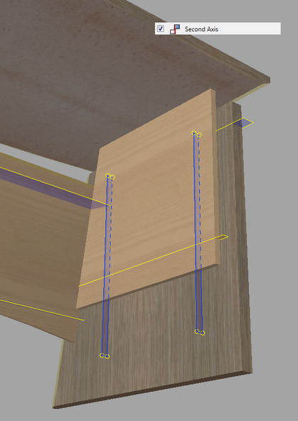
Move to the last assembly constraint of the Second Axis and select vertical axes as shown in the figure below.
Then click the "Attach" button. If you change the representation mode to Wireframe, you will see that four Confirmat.ipt components are arranged in the proper places.
Follow the same steps with the other side of the table if two nestled board tables were not selected during the first selection.
Arranging minifix dowel joints
Restart the hardware component placement command Then in the appearing window open the insert component command
Find Minifix D15.ipt component in the library path Fixed joints\Minifix joint and open it.
The dialog box is filled with Minifix D15.ipt component assembly constraints. Select assembly constraint reference geometry for Nestled Board Plane. Select the plane as shown in the figure below.
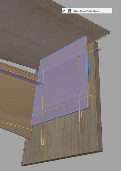
In the dialog box, move the cursor to the next assembly constraint – Pillar Board Side Plane. Select the planes as shown in the figure below.
To make the explanatory figure easier to understand, it does not show that you can also select an analogous pillar board side plane in the other side of the table. In this case, you can select planes on both sides and move to the next assembly constraint reference geometry setting. In this case Minifix D15.ipt components will be automatically arranged on the other side of the table as well. After you move to the last Axis assembly constraint, select Axis planes based on which Minifix joint will be arranged.
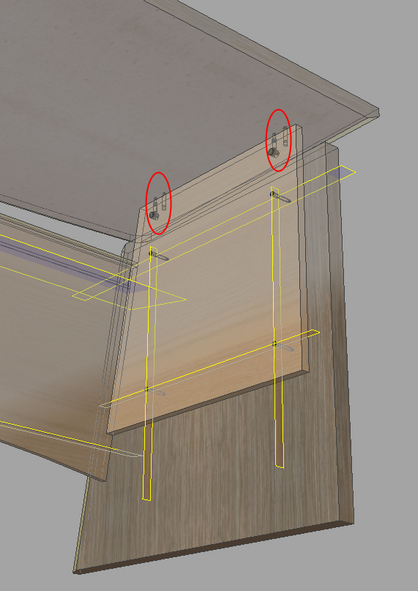
Then click the "Attach" button. The figure below shows the results of your work.
Follow the same steps to tighten up the front plane to the side legs using Minifix D15 connector.
The figure below shows the result of your work.
Using the same method, the remaining connectors are arranged where required.
|


First you have to change the Enabled status of all Woodwork for Inventor components to Disabled. To do this, open Woodwork for Inventor command that controls component visibility. Woodwork Design –> Visibility Control –> Components
In the appearing component control window, turn component visibility off.
If you have a closer look at the situation at hand, you will see that for some hardware components the wooden dowel must be repositioned to the opposite side.
Minifix D15.ipt component is an iPart type component with a default configuration of a wooden dowel in the left or right. The repositioning of the wooden dowel is performed in two steps: 1. First, you have to reconfigure one Minifix D15 component occurence having incorrect dowel position. 2. Then the same configuration is applied to other occurrences of the same component having incorrect dowel position.
Occurrence reconfiguration
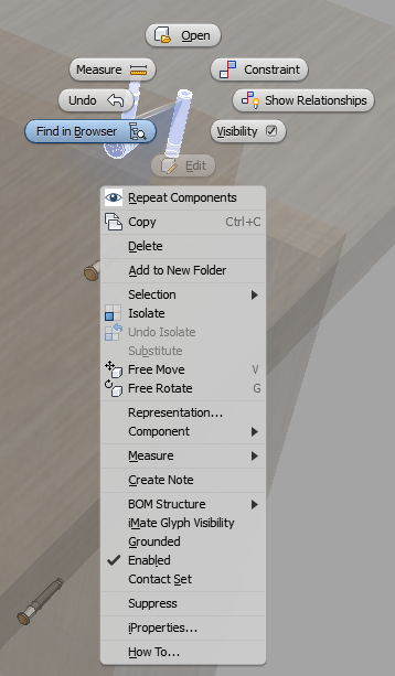
To reconfigure a component occurrence, find one of the Minifix D15.ipt occurrences that requires dowel repositioning. Select the occurrence to be changed in the model and right-click to open a context menu.
After selecting Find in Browser command, the component being searched will be selected in the side browser. After expanding the component composition and putting the cursor on the Table node, select Change Component using the right context menu.
In the table, select the Side position Right value and click “OK”.
Then you will see how a component occurrence changes its configuration from left to right.
Applying the same configuration to other component occurrences
Start the Woodwork for Inventor command for copying configuration form one occurrence to another. Woodwork Design –> Joint –> iMatch
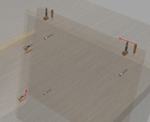
Select the occurrence that has just been changed (1). The command switches to the status where you need to indicate another occurrence of the component of the same origin. Using the cursor, select the occurrences to be changed (2;3;4). Each of them are now changed to right hand side configuration.
Then open the component visibility control command Components After checking the box next to Woodwork Components Visibility Enabled, all components containing Woodwork for Inventor material will be enabled.
|


Open the Sculpt command for automatic hole generation based on the arranged hardware. Woodwork Design –> Joint –> Sculpt
Then click the "Sculpt" button. To make sure that the sculpting was completed successfully:
The latter command turns off the visibility of all Purchased type hardware components. In the screen you will see holes left in the parts after completing the Sculpt command.
To save changes, press "Ctrl+S". |